| A sectional view is distinguished from an outside view by section lines or hatching drawn on the cut surfaces produced by the section plane, see Figure 3.1 Thin lines inclined at 45° are used for hatching. They are equally spaced by eye, the spacing being not less than about 4 mm. The larger the area to be hatched the wider the spacing may be, up to a maximum of about 10 mm. For very large areas the hatching may be limited to a zone following the contour of the hatched area, as shown in Figure 3.3. 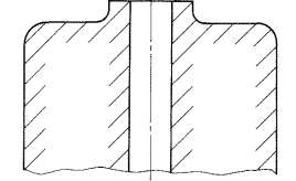
Figure 3.3 Hatching large areas It is important to the appearance of the finished drawing that hatching is drawn carefully. The spacing must be consistent, not too close, and the lines must touch the outlines of the section and be thin. When a single component is sectioned, as in Figure 3.4(a), the slope and spacing of the hatching must be the same throughout the view. On an assembly drawing the slope of the hatching must be reversed on adjacent parts, as shown in Figure 3.4(b). For each component the slope and spacing of the hatching must be the same on all views on the drawing. If more than two parts are in contact the angle of the hatching may be changed from 45°, or the spacing may be varied to avoid the impression that it is crossing outlines, hatching never crosses outlines. 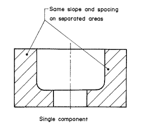 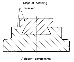
- (b)
Figure 3.4 Sectioning on adjacent components |
 Resource Centre
 Student Stationery
 Media Centre
 Student Portal
 Refer to the Student Portal for additional resources related to this module.